The Finished Computer
With input and output attached, we have a whole computer. From here on, we look at the programs that run on this machine, that is, software. We can’t look at every part of the computer each time we look at a program, so before that, let’s sum up the machine once and decide how to draw it more simply from now on.
Summary
- The PC points to a slot in memory.
- The control unit decodes the instruction in that slot and operates each part.
- The registers and the ALU work as operated.
- The PC moves to the next slot, or to another slot if it’s a jump.
- Input and output devices exchange numbers through designated memory slots.
This computer is also a sequential circuit. All the bits in the registers, memory, and PC are its state, and on each clock it makes the next state by the rule the current instruction sets.
Let’s do multiplication on the machine we finished in the input and output post. The CPU has no multiply instruction, but adding the multiplicand as many times as the count gives the product. Memory holds a program that multiplies the numbers in two input device slots (13 and 14) and sends the result to the output device (15).
Press the play button to the right of CLK to give clocks automatically. 3 is added four times, and 12 shows on the output device.
Drawing it simply
When running a program, we only actually watch a few things, so from now on let’s keep just those and draw it like this. Only the instruction lines in memory and the registers are shown, and the highlighted line is the slot the PC points to.
Runs from address 0.
- Press play to run the same multiplication as above to the end. R2 ends up with 3 × 4 = 12.
- Press reset, then press next to run one line at a time.
- Press reset, change the values in the R0 and R1 boxes, and run it again.
The von Neumann architecture
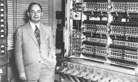
With the CPU, memory, and input and output devices, we have a whole computer. This way of building a computer from these three was first laid out in a 1945 report by John von Neumann, so it’s called the von Neumann architecture. Almost every computer today, from smartphones to supercomputers, follows it.
Its defining trait is that instructions and data are stored in the same memory, as the same kind of numbers.
Wrapping up
In the next post, let’s keep the machine as it is, change only the program in memory, and have this computer do something entirely different.
Challenge
With R1 = 0, we run from address 0. What is R1 after the instruction at address 3 has run? Answer with a number.
Address 0: LOAD 3
Address 1: STORE 2
Address 2: ADDI R1, 1
Address 3: ADDI R1, 3